Design Of Large Span Steel Structure Space Tube Truss

I. Space Tube Truss Structure
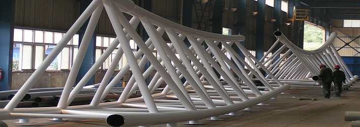
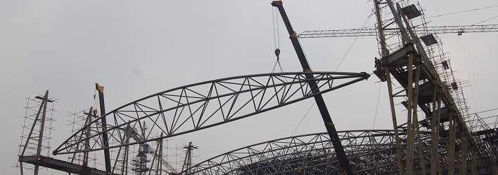
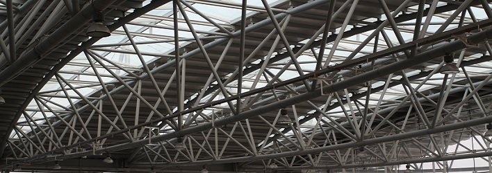
1. At this stage, in the construction of various large-scale construction projects such as civil buildings and industrial buildings, the application of space tube truss structures is becoming more and more extensive. Different arrangement of rods will lead to the formation of differentiated force characteristics of tube trusses. The tubular truss structure can be divided into two forms: space and plane. The planar tubular truss structure, that is, the web members and the upper and lower chords, are all located on the same plane. However, the out-of-plane rigidity of this structure is relatively weak, and it is easy to cause out-of-plane instability. When the web rod and the upper and lower chords are located on the triangular section to form a spatial structure, the applicable span of the structure can be enlarged and a better spatial stability can be formed, and a good aesthetic appearance can be constructed at the same time. When the out-of-plane supports cannot be effectively arranged, the larger-span spatial roof structure can adopt the spatial triangular tube truss. This form presents better stability, and the number of supporting members used is small, so the cost is lower.
2. Square, round, and rectangular are the main types of cross-sections of pipe truss connectors. When circular connectors are used, C-C truss should be used; when positive connectors are used, R-R should be used; when using rectangular connector section, R-C type truss should be used.
3. The shape of the truss will be directly affected by the type of chord. Generally, curved trusses and linear trusses are the main ones. From the perspective of improving the aesthetics of the building, the curved truss presents a higher application advantage. In order to reduce the construction cost, the actual When designing a curved tubular truss structure, rods in the form of straight rods can be used, and the curve can be replaced with an approximate broken line. The application of steel pipe truss structure for design and construction can not only improve the appearance of the construction project, but also reduce the cost. Compared with other construction materials, the materials used in the process of applying the steel pipe truss structure are more reasonable, which is in line with modern construction engineering.


II. Key Points Of The Design Of Large Span Steel Structure Space Tube Truss
1. Butt joint design of supervisor with unequal wall thickness
The supervisor-to-interface is in a large-span variable cross-section, and the phenomenon of unequal wall thickness is often generated. In response to this problem, in actual work, the designer usually requires the manufacturer to strictly carry out the internal groove processing of all the supervisor’s interfaces. At the same time, in order to meet the requirements of acting as a gasket, it is also necessary to apply the folded plate. However, the application of most internal groove components in actual construction shows the characteristics of difficult construction and long time-consuming construction. In addition, compared with developed countries, my country’s seamless pipe manufacturing technology still has a certain lag, so the coiled pipe manufacturing method can be fully applied, but the formation of the difference in the roundness of the straight seam steel pipe in this process is inevitable. According to relevant construction regulations, it is strictly forbidden to produce ±0.75% straight seam steel pipes and bending deviations with an outer diameter deviation rate greater than 3.0 mm/m. In the welding of two components, when the two have different thickness and width, when one side of the weldment has a thickness of more than 4 mm, the thickness and width should be taken from two angles, along one side or both sides. Bevel angle, 1:1.25 is the maximum slope control parameter of the bevel angle.
2. Design of K-type lap joints
From the point of view of node structure, overlapped nodes can usually be divided into three types, namely full overlap, partial overlap and gap overlap. When designing nodes with different structures, the lap method must be scientifically selected and controlled to avoid an increase in the number of hidden welds. Generally speaking, the diameter ratio between the main pipe and the web rods should be strictly controlled in the design. The value range of the two should be controlled within the range of not less than 0.2 and not greater than 1, and the amount of overlap between the web rods should be controlled within Not less than 25%. In the process of selecting nodes, attention should be paid to taking effective measures to replace overlapped nodes with gap nodes. This is because gap nodes are easier to assemble and convenient to construct than partially overlapped nodes. Under normal circumstances, welding construction cannot be applied to the hidden parts of partially overlapped joints, and only when the unbalance coefficient of the main pipe and web members is greater than 1.5, welding can be applied to the partially overlapped joints. When selecting overlap joints, attention should be paid to overlapping the 25% width of the overlapped tube and the overlapped tube. At the same time, for partially lapped K-type nodes, when the vertical internal force of the main pipe is less than 1/5 of the internal force of the abdominal tube, the toe of the lapped member cannot be welded at this time. In addition, for lap joint components, the ratio between the diameter of the outer layer of the tube and the thickness of the component wall cannot be greater than 100. Under normal circumstances, the overlap rate of K-joint members should be strictly controlled, and this value should not be less than 25% and not more than 100%. When web rods with different thicknesses are produced in the design and construction, the thin-walled pipe should be placed on top of the thick-walled pipe during the actual welding construction. It can be seen that in the actual design of the space tube truss, the bearing capacity of the member nodes and the members should be intensively considered, and the structure of the node should be highly valued. In the process of designing the node structure, the overall consideration of each member is to lay a foundation for other design links.
3. Construction design of space tube truss
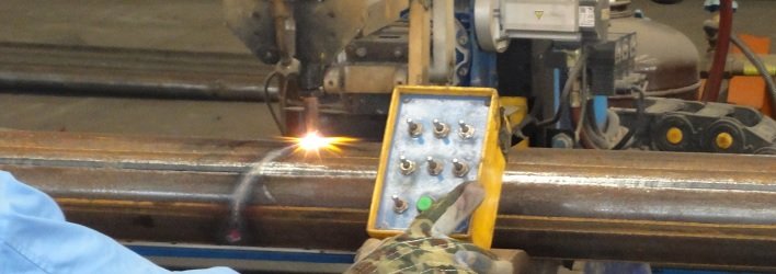
In the actual deployment of the space tube truss construction process, the main procedure to be followed is “spot welding first, then full welding”. When the lap joints exist in the construction of the truss, the construction personnel must clearly deal with the welding overlap parts That is to say, in the actual construction process, the installation sequence of each component should be fully confirmed to avoid reversing the component installation sequence, which may cause serious safety hazards during construction and later use. In the process of installing space tube truss, start with the following installation sequence: install the branch pipe on the basis of installing the main pipe. After completing the installation of a branch pipe, the straight pipe toe should be welded directly, and finally the weld welding can be applied to the branch pipe and the branch pipe.
4. Intersecting mouth patch design
The entire design and construction process of a construction project has the characteristics of strong system and complexity. In the actual construction process, there are relatively many factors that affect the quality of the project. Human errors and equipment errors will affect the entire project design and the construction causes serious errors, and the existence of these factors will cause excessively large gaps to occur in the gaps of the intersecting ports. Therefore, only the timely implementation of the inspection and repair of the gaps can reduce the probability of the occurrence of excessively large gaps in the intersecting ports. First, when there is a gap length between the truss and the main chord that exceeds 8 mm, in the process of dealing with this problem, the intersection should be completely replaced, and part of the structure around the intersection can also be cut. The actual cutting process should be oblong, the length should not be less than 500 mm, and the cut part should be replaced, and bevel welding should be carried out during the replacement construction; second, when there is an excessively large branch pipe intersecting gap, Patches of local components at the intersection of branch pipes should be implemented, oblong patches should be used to ensure that they have a length of not less than 300 mm, and bevel welding should be used.


